Laboratory Training 1
Design of Algorithms
1 Training Tasks
1.1 Implementation of a Branching Algorithm
Implement an algorithm for solving quadratic equation. The algorithm should consider all possible data. In particular, the discriminant should be checked, and it should be checked whether the equation is quadratic. If the equation degenerates into a linear one, it is necessary to provide for finding the root of this linear equation, or to establish the presence of infinite count of solutions (absence of solutions). Use the UML Activity diagram for algorithm presentation.
1.2 Implementation of a Looping Algorithm
Implement an algorithm for calculating the following expression (integer values of x, n and k are
entered by the user):
In the given sum, the common element can be written as i/(x + 2i), but it omits one element when i = k.
Use the UML Activity diagram for algorithm presentation. Provide a check of possible errors.
1.3 Individual Assignment
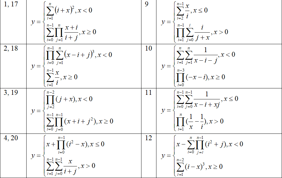
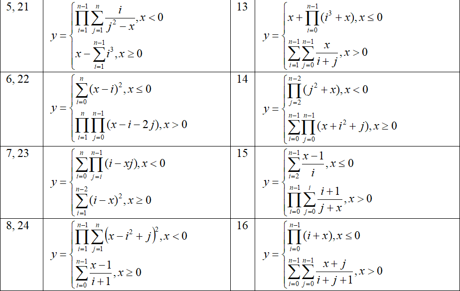
You should develop an algorithm of a program that calculates values of a function in a given range. Your program should read interval boundaries, step of argument increasing, and n value.
Your algorithm should be represented using the UML Activity diagram. It should contain such parts:
- data reading
- main loop, in which you set a new value of an argument and show both this value and calculated value of a function; then need to increase the argument value.
The particular function is given in the individual task according to your own index in the group students list (index of variant).

2 Instructions
2.1 Basic Concepts of Computer Science
2.1.1 Numeral Systems
A numeral system is a set of rules and symbols that allows encoding any number. The most common are positional numeral systems (positional notations), in which the value of a digit depends on position in the number representation.
The positional numeral system is concerned with the concept of base (radix) of notation. Any number can be represented as a sum of sequential powers of a radix multiplied by values of the relevant digits. The base or radix is also the number of unique digits that a positional numeral system uses to represent numbers. As radix we can use any number not less than two. The Name of notation corresponds to its base (decimal, binary, octal, hexadecimal, and so on). In everyday practice, we use the decimal notation.
The binary notation traditionally used in computing. All data is represented using sequences of zeros and ones. This notation has two main advantages:
- to represent the numbers 1, a non-zero electronic signal is used; because the signal amplitude does not matter, it significantly improves the reliability and data storage;
- rules of arithmetic are very simple and can be easily implemented by hardware.
The disadvantages of the binary notation include awkwardness and lack of visibility. In cases where binary representation is important, we can use other notations which bases are powers of two. In the previous decades octal notation was used. Now the most used is hexadecimal notation (with base 16). A hexadecimal digit is the one of the ten decimal digits or the one of the letters A (10), B (11), C (12), D (13), E (14), and F (15).
The table below shows a decimal, binary and hexadecimal representation of numbers from 1 to 32:
| Decimal | Binary | Hexadecimal | Decimal | Binary | Hexadecimal |
|---|---|---|---|---|---|
| 1 | 00000001 | 1 | 17 | 00010001 | 11 |
| 2 | 00000010 | 2 | 18 | 00010010 | 12 |
| 3 | 00000011 | 3 | 19 | 00010011 | 13 |
| 4 | 00000100 | 4 | 20 | 00010100 | 14 |
| 5 | 00000101 | 5 | 21 | 00010101 | 15 |
| 6 | 00000110 | 6 | 22 | 00010110 | 16 |
| 7 | 00000111 | 7 | 23 | 00010111 | 17 |
| 8 | 00001000 | 8 | 24 | 00011000 | 18 |
| 9 | 00001001 | 9 | 25 | 00011001 | 19 |
| 10 | 00001010 | a | 26 | 00011010 | 1a |
| 11 | 00001011 | b | 27 | 00011011 | 1b |
| 12 | 00001100 | c | 28 | 00011100 | 1c |
| 13 | 00001101 | d | 29 | 00011101 | 1d |
| 14 | 00001110 | e | 30 | 00011110 | 1e |
| 15 | 00001111 | f | 31 | 00011111 | 1f |
| 16 | 00010000 | 10 | 32 | 00100000 | 20 |
Formally, the base is usually indicated as an index of the number. For example,
There are several ways to obtain numbers in various number systems. The most common way to convert from decimal notation to other number systems is a multiple division of the initial number and intermediate results onto the base of the number system and obtaining an integer part of division. The last result and the remainders received are copied in the reverse order. For example, in this way you can get a binary representation of 25:
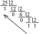
Copying the last result and remainders from division, we get
The inverse transformation is carried out by finding the sum of the products of numbers and descending powers of the base:
To convert a number from binary notation to hexadecimal notation every four bits, from right, should be replaced with a single hexadecimal digit. The reverse conversion is similar: each hexadecimal digit should be replaced by four binary digits.
2.1.2 Units of Information Measurement
Units of information measurement are used to quantify the volume of data.
Bit is the smallest unit of information that can be represented as 0 or 1. In some cases sufficient to store information about the false or truth of a certain statement, for example, the presence of a certain options in the program.
Byte consists of 8 bits. A one byte-byte cell can be used to store a small integer or character of text.
Note: the use of single-byte cells does not correspond to modern ideas about character storage; In most cases, a two bytes long cell (16 bits) is used for a separate character.
Units of measurement information derived from byte given in the table:
| Name | Abbr. | Definition | Number of bytes | Use |
|---|---|---|---|---|
| Kilobyte | KB | 1024 bytes | 1 048 576 bytes | to determine the size of small files, such as text documents |
| Megabyte | MB | 1024 kilobytes | 1 073 741 824 bytes | to determine the size of large files such as images and audio files |
| Gigabyte | GB | 1024 megabytes | 1 099 511 627 776 bytes | for measuring the capacity of external media and memory sizes |
| Terabyte | TB | 1024 gigabytes | 1 125 899 906 842 624 bytes | for large capacity, for example, in modern hard drives and data centers |
| Petabyte | PB | 1024 terabytes | 1 152 921 504 606 846 976 bytes | in the context of storing big data (cloud services) |
| Exabyte | EB | 1024 petabytes | 1 180 591 620 717 411 303 424 bytes | in the context of large data centers |
| Zettabyte | ZB | 1024 exabytes | 1 208 925 819 614 629 174 706 176 bytes | to quantify global data storage and transfer capabilities |
| Yottabyte | YB | 1024 zetabytes | 1 237 940 039 285 380 274 899 124 224 bytes | to discuss potential future data storage needs |
These units of information measurement are widely used in computer technology, telecommunications and other fields, related to data processing and storage.
2.1.3 Computer Presentation of Numeric Data
Regardless of the type of computer and programming language, all data stored and processed can be shared on data with a fixed point (integer data) and with a floating point (real data). All other data (text, images, sound, video, etc.) encoded by integers or real numbers.
A cell of 1 to 8 bytes is usually created to represent an integer. Positive numbers are presented directly in the binary system. Negative numbers are presented in the so-called two's complete code. To get a negative number representation bits, you should invert the binary representation of the absolute value of number and add 1. For example, for small integers, which are located in one byte long cell:
| Number | Presentation of absolute value | Inverted Bits | Two's complete code |
|---|---|---|---|
| -1 | 00000001 | 11111110 | 11111111 |
| -2 | 00000010 | 11111101 | 11111110 |
| -10 | 00001010 | 11110101 | 11110110 |
The older bit of representation of the integer is used to indicate that the number is positive (0), or negative (1). When other bits are not enough to represent a positive number, increasing the number we suddenly get negative value:
127 + 1 = -128
127 + 2 = -127
In programming languages in which the effectiveness of the program is of great importance (C, C++, Java, etc.), this situation is not checked, because such a test would slow down the execution of the program. In some languages (e.g. C#), such verification can be temporarily turn on.
In some programming languages, in the case of overflowing of an integer cell, a new lager cell is automatically created, in which the previously obtained value is copied. This approach is convenient for the programmer, but very inefficient.
Real numbers (floating point numbers) are usually represented in the form
mantissa × 2 exponent
The number of bits for representing the mantissa and the exponent can be different. Converting numbers into human-readable form is carried out during the output to the screen or on the printer.
2.1.4 Software
The word program is used in two ways:
- to describe individual instructions, or source code, created by the programmer;
- to describe an entire piece of executable software.
Hardware is the physical, touchable, material parts of a computer or other system.
Software is a set of software programs and documents necessary for operating these programs. Software can be classified into such parts as:
- System software - computer software designed to operate and control hardware
components and application programs; it includes:
- operating systems;
- service utilities;
- DBMS (database management systems)
- device drivers;
- Application software includes programs and packages designed to solve problems of users in specific domains; application software include word processors, graphic editors, polygraphic systems, programs for scientific and technical calculations, games and so on;
- tools - software designed for creating other software; tools include compilers and other tools for linking and debug, integrated development environments (IDE), and CASE-system (Computer-Aided Software Engineering).
An application is a synonym for computer application program. This term can be also applied to any program that is not part of the operating system.
2.1.5 Operating Systems
An operating system is a set of software tools that manage all resources and processes of a computer system. Resources are processor, memory, display, and peripherals (external devices). Processes are separate programs, which obtained necessary resources and launched for execution.
Components of operating systems can be grouped as follows:
- kernel (scheduler, device drivers, network support, file system);
- system libraries;
- utilities.
Examples of operating systems are MS-DOS, OS/2, macOS, MS Windows of various versions, UNIX, Linux, Solaris, Google Android, etc.
2.1.6 File System
A file system is a set of methods and rules for the organization and storage of directories and files on the external device. Sometimes file system also means a set of files and directories on a specific device.
File systems are classified into hierarchical file systems (files and subdirectories can be arbitrary nesting) and flat file systems (set of files without subdirectories). Hierarchical file systems are currently most used. There are special types of file systems:
- clustered file systems can distribute files across multiple physical devices of the single computer;
- network file systems provide mechanisms for file access one computer from other computers on the network;
- distributed file systems provide file storage by their distribution between multiple computers on the network.
The file system is usually considered as part of the operating system. Each operating system provides a set of file systems. For example, file systems FAT 16, FAT 32, NTFS associated with Windows, Ext2, Ext3, Ext4 used in Linux.
2.1.7 Text Files and Binary Files
Regardless of the file system, all files can be divided into text files and binary files.
A text file is a computer file in which all the information is represented in the form of characters
(symbols) of a particular character set. The sequences of characters are split into lines. To separate lines
from each other special separators are used (one or more special control characters). Examples of text files are
simple documents created using notepad (*.txt), the source code of programs (*.pas,
*.c, *.cpp, *.cs, *.java, etc.), hypertext markup files
(*.htm, *.html), formatted documents (*.rtf), and so on. Preparation and
editing text files, regardless of their format and special purpose can be done using universal text editors,
such as Notepad.
A binary file is a computer file in which data are represented using binary numbers, according to an
internal representation in memory (not by symbols as in text files). Every single binary file format requires
special software. Examples of binary files are executables (programs) under all operating systems, raster images
(*.tif, *.jpeg, *.png, *.gif, etc.), archives
(*.zip, *.rar, etc.), audio files and video files of all formats, binary code files
(*.obj, *.class, etc.), as well as many special formats of software packages.
2.2 Basic Concepts of Programming
2.2.1 Programming Languages
A programming language is a special notation designed to set instructions to a computer. Programming languages can be classified as low-level languages and high-level languages.
- low-level languages designed for a specific computer and reflects its machine code; this group contains machine instructions and assembly language;
- high-level languages are independent of the internal machine code of any particular computer. Programmers can work with abstract data.
High level languages are divided into the following groups:
- procedural (FORTRAN, ALGOL-60, BASIC, ALGOL-68, PASCAL, C, Modula-2, etc.);
- object-oriented (Simula-67, Smalltalk-80, C++, ADA, Object Pascal, OBERON, Java, C#, etc.).
There are also languages of functional, logical, declarative programming, etc.
2.2.2 Interpreters and Compilers. Stages of Program Development
The instructions of high-level programming language should be translated into machine code by a special program called translator. Translators can be of two types: interpreters and compilers.
- An interpreter translates a program as it reads it, turning the program instructions, or code, directly into actions; examples of interpreters are BASIC, JavaScript, etc.; interpreters provide flexibility and create effect of instant performance, but the need for multiple translation of previously interpreted lines at runtime significantly reduces the effectiveness of the program;
- A compiler translates the code into a set of commands that can execute processor or virtual machine; programs written in Pascal, C++, C# and many others, are always processed by compilers.
Typical stages of program development are the following:
- a source code of the program being prepared by text editor;
- the source code is translated into a set of binary instructions (binary code); it can be machine code, as in C++, or intermediate binary code, as in Java;
- compiled code is linked from individual parts and executed.
Unfortunately, almost every program, no matter how trivial, can have errors, or bugs. Program execution in order to identify errors and verify compliance with algorithm is called debug.
2.2.3 Types of Applications
Applications that are created in modern programming environments in terms of user interaction can be divided into two main groups:
- console applications;
- graphical user interface applications (GUI applications).
Console applications run in a special console window or in full-screen mode. To enter data, keyboard (standard input device) is used. Data can be read either as command line arguments (after the name of the program in the command line) or at runtime.
The common logic of console applications is built on so-called data-driven paradigm. The overall structure of the program includes input of initial data, computing and display results. During the calculations, based on data and intermediate results, branching, looping, or subroutine call can be done.
GUI applications provide user interaction through graphical controls (buttons, menu items, list items, scroll bars, etc.) and various technical input and positioning devices (keyboard, mouse, joystick, etc.). The results can also be displayed in windows or dialog boxes in the form of text, graphics, etc.
The complex interaction logic prevents data-driven programming techniques. Instead of it, event-driven paradigm is used. The entire program consists of initialization (registration visual controls) and the main loop of receiving and processing events. Examples of events are moving or clicking mouse, keyboard input, and so on. Each registered visual control can receive events related to it and perform processing event handlers - functions that process these events.
Typically, you create one or more windows, and then you add visual controls to these windows. For these items you can create and register event handlers. The basic cycle of receiving and processing events is performed by standard means (through application framework). Developers of particular program only need to add the necessary elements and write functions for handling events.
2.3 Algorithms
An algorithm is a detailed description of the sequence of actions aimed at solving a particular problem. The goal of the algorithm is to be achieved by the finite number of steps. Algorithms are usually divided into linear algorithms, branching algorithms and cyclic algorithms.
We can represent algorithms in several ways:
- verbal description
- pseudocode (artificial algorithmic language)
- graphical representation
The graphical representation is more descriptive. There are two standard forms of graphical algorithm representation: traditional flowchart (block diagram) and activity diagram.
The present-day representation of flowcharting is based on Unified Modeling Language. Unified Modeling Language (UML) allows graphical representation of models of complex software systems. UML gives a set of diagrams for visualization of systems' design. A diagram is a graphical presentation of a collection of model elements, most often rendered as a connected graph of relationships and other model elements.
An activity diagram is one of standard UML's diagrams. Activity diagrams are very similar to flowcharts because you can model a workflow from activity to activity. Activity diagrams can be used for representation of algorithm.
Typically, Activity diagram includes such elements:
- Initial State
- Activity
- State Transition
- Decision Symbol
- Final State
It is always necessary to describe the initial state. The initial state is represented by a large black dot. The only initial state can present on a diagram.

Each activity represents a particular state within the execution of the encompassing method.
Activities are linked by automatic transitions, represented by arrows.
UML defines an optional stereotype for displaying decisions. A decision is represented by a rhombus with several transitions coming out of it.
A final state is represented by a big black dot surrounded by a circle. One diagram can contain several final states.

One and only one arrow issues from the initial state. An action element requires one arrow to enter and one to exit. There should be no operation without any arrow. Multiple arrows can only come from the decision symbol.
2.4 Classification of Algorithms
Most of the problems of algorithmization can be solved using the three simplest types of algorithms:
- linear algorithms;
- algorithms with branching;
- cyclic algorithms.
There are also more complex algorithms associated with the use of routines, for example, recursive ones.
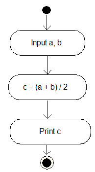
The following diagram shows an algorithm for finding of arithmetic mean (average value). This is a typical linear algorithm without branching and loops, because all actions are performed once, and under any conditions:
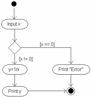
An algorithm that calculates reciprocal value requires checking whether the divider takes the value 0 or not:
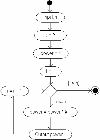
Cyclic (looping) algorithm involves performing certain calculations several times. All these
actions that are repeated cyclically are called the body of the loop. Before the start of the loop or
after the action in the body we need to verify the necessity of re-entry into the body of the loop. The
following algorithm describes the actions associated with the reading of an integer value (n) and
finding powers of 2: from the first to the n-th:
When creating algorithms using activity diagrams, individual messages can be displayed in any human language, because the diagram is not associated with a specific programming language and its software implementation is performed manually. The main thing: the diagram should be understandable to the executor.
3 Sample Algorithms
3.1 Linear Equation
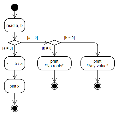
An example of a branching algorithm (without looping) is an algorithm for solving a linear equation:
If a is not equals to zero,
If both a and b are zeros, any value can be treated as the root of an equation. If b is non-zero value, but a is not, equation cannot be solved. This should be displayed on the diagram:
3.2 The Calculation of Sum
Cyclic algorithms are very often used to calculate sums of sequences. Suppose we need to read the value n and calculate such sum:
The algorithm for calculating the sum may look like this:
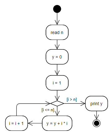
As can be seen from the algorithm, first we assign 0 to the result, and then at each step we add the next summand.
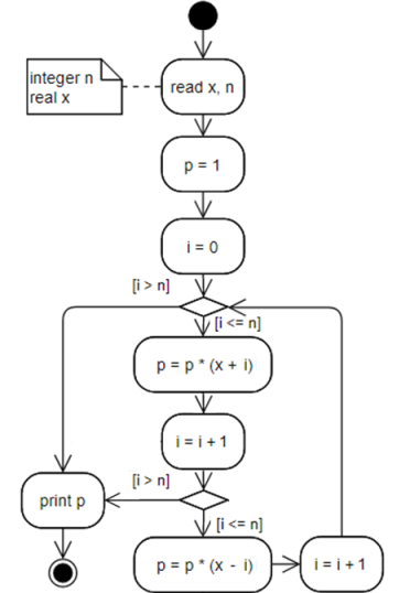
3.3 Calculating the Product
The calculation of products is typically implemented through assigning the result of the initial value of 1 and the sequential multiplication of the current result and the next multiplicand. Suppose it is necessary to calculate such a product:
Additional problem is concerned with alternating signs in multiplicands. There is common solution of this
problem: we create a special additional coefficient (for example, k), which is sequentially equal
to 1 or –1. Calculation of powers of –1 does not make sense in any case. The algorithm may be
like that:
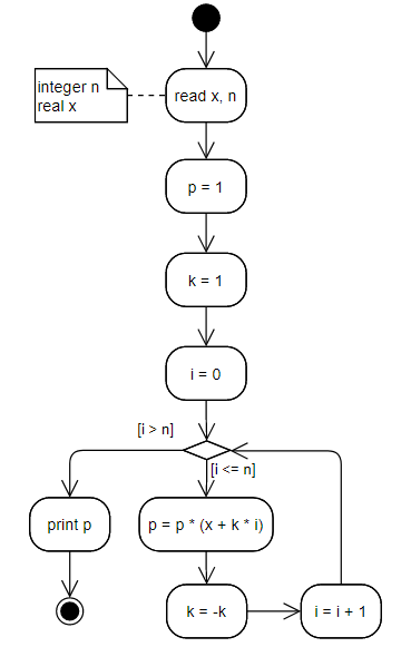
The diagram above contains so-called annotation, the arbitrary text with an explanation that can be linked to a certain element.
An alternative solution is a parity check of i. This is always possible.
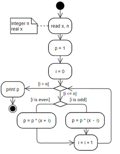
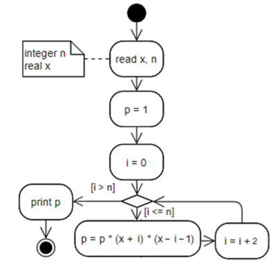
Another alternative solution involves a calculation in two stages at each step of the cycle:
If it is known for sure that n it is always odd, the algorithm can be simplified and nothing additional can be
checked in the body of the loop:
3.4 The Sum of Products
Sometimes, there is a need to realize the nested loops. For example, when we need to get the sum of all cells of a rectangular table or calculate the sum of products, the sum of sums, the product of products, etc.
It is necessary to enter the value of n and calculate y by the formula
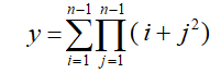
We need to start with the analysis of the task. We can present a formula in a more convenient form:
For example, if n is 4, we get:
The algorithm can be as follows:
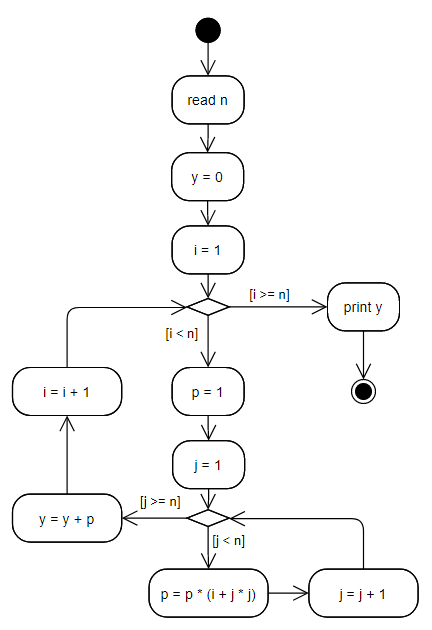
It is important to initialize the inner product with initial value (1) on each step of outer loop.
3.5 The Product of Sums
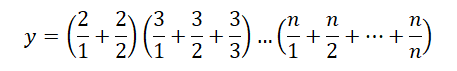
Another example of implementing an algorithm with nested looping is the calculation of the product of sums. It is necessary to enter the value of n, calculate y by the formula
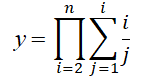
and show the result.
As in the preceding example, we can represent the formula in a more convenient form:
Before calculations, it is necessary to check whether the value of n, which was entered by user, more than or equal to 2, otherwise the formula loses sense and an error message should be displayed. The algorithm can be as follows:
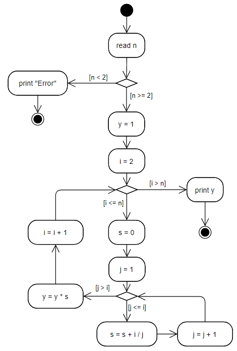
Similarly to the previous example, it is very important to initialize the internal sum every time at each step of the external cycle.
3.6 General Algorithm of the Individual Task
According to the individual task, it is necessary to create an algorithm of the program of calculating values of the function in a given range. The total algorithm frame may be like that:
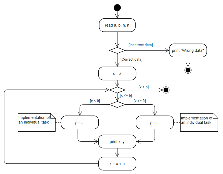
You should describe the possible options for incorrect data in more detail, and you should ensure the condition of the individual task.
4 Exercises
Exercises are performed by students who want to get an excellent grade.
Task 1
Develop an algorithm of the program that reads some distance in inches and shows it in millimeters (1 inch = 25.4 mm).
Task 2
Develop an algorithm of the program that reads eight values and returns an average.
Task 3
Develop an algorithm of the program that reads value of integer variable n and returns n!
5 Quiz
- What is a positional notation?
- What is a base of the numeral system?
- What are advantages and disadvantages of binary notation?
- What is the usage of the hexadecimal notation?
- What are the units of information measurement?
- How are negative integers represented in computer memory?
- How are real numbers represented in computer memory?
- Define the concept of software.
- How can classify software?
- What are tools?
- What is application?
- List the functions of the operating system.
- Give examples of operating systems.
- What is a file system?
- What is the difference between text files and binary files?
- Give examples of text and binary files.
- What determines the level of programming language?
- How to define the term "computer program"?
- What are the stages of program development?
- What is debugging?
- What is console application and how it differs from other types of applications?
- What are the advantages and disadvantages of interpreters and compilers?
- What is an algorithm?
- What are ways of algorithm representation?
- What are the different types of algorithms?
- What is UML?
- What is UML diagram?
- What is the difference between block diagram (flowchart) and activity diagram?
- What is the difference between representation of decision elements in block diagram (flowchart) and activity diagram?
- What is the difference between representation of output and calculation in Activity diagram notation?